


QIANLI Thermal Imager Camera for Mobile Phone PCB Troubleshoot

- Availability: Out Of Stock
- Product Code: PFMLT02
1. Product introduction
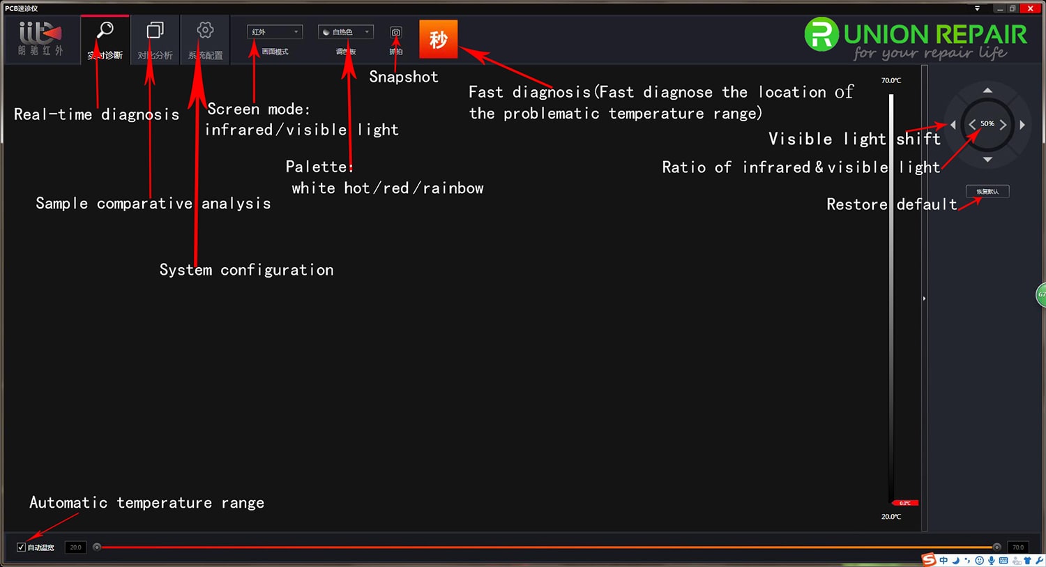
Figure 1: PCB quick diagnostic apparatus
PCB quick diagnostic apparatus is a new generation of maintenance equipment, which is the world's first to use dual-spectral interleaved positioning technology. Through powerful PC-side intelligent analysis software, the use of intelligent algorithms, it can detect the motherboard chip operating temperature by the use of intelligent technology. By the normal / abnormal motherboard comparison analysis, it can quickly and accurately identify problem chip, which can assist maintenance personnel in overhauling the problem board, greatly improve the efficiency and maintenance accuracy.
PCB infrared thermal imaging diagnostic apparatus is composed of three parts, the front-end detection host, and adjustable lift bracket and computer client analysis software.
The front end host is composed of visible and infrared dual vision lens, which can display visible light screen, infrared thermal imaging screen, visible light / infrared thermal imaging fusion screen. It can locate the position of problematic chip quickly by observing the different screen switch. Besides, the visible lens can be uninstalled to replace electron microscope lens anytime, which can be used as electronic microscope, a machine with multi-function. In order to reach the best observation distance, it comes with the adjustable bracket. By adjusting the distance between the machine and PCB, it can have the best clear imaging effect.
By Computer client analysis software, intelligent identification algorithm, running temperature of each chip on PCB board can be displayed on the screen and the maximum temperature value of the chip can be also intelligently positioned .Through the normal / abnormal motherboard comparison analysis, quickly locate the problematic chip position. At the same time the software can take pictures, video to reserve maintenance motherboard photos, video proofs, to provide reference comparison date for future maintenance.
2.Product features
- Detection host, lifting bracket with removable design, easy to assemble, carry
- The visible lens can be disassembled and replaced with electron microscope lens to act as electronic microscope, a multi-purpose machine
- Bracket can be adjusted by knot to reach best observation distance
- Visible light and infrared thermal imaging dual light lens showing different picture effects
- Visible / infrared thermal imaging dual light fusion, showing a more delicate picture effect
- The software intelligence recognition algorithm can display each chip temperature value
- Through the normal / abnormal motherboard comparison analysis by software, quickly locate the problematic chip
- The software side can record each time maintenance motherboard photo data by taking picture and video
3.Parameters
| Infrared part | |
| Detector type | Uncooled VOx detector |
| Resolution | 160x120 |
| Spectrum range | 7.5-13.5 μm |
| Lens angel | 57°Â44° |
| Visible part | |
| Resolution | 1920x1080 |
| Interface and display | |
| Output mode | Visible / infrared thermal imaging / infrared fusion |
| Video output | RJ45 |
| Storage | Standard 32G micro SD card |
| Video storage format | 8bit H264/14bit TIFF |
| Image storage format | JPEG/TIFF |
| Physical characteristics | |
| Bracket dimension | 38cmx25cmx36mm |
| Weight | 2.8kg include bracket |
| Installation | Detachable installation |
| Power | |
| Input power voltage | 5-26 VDC |
| Consumption | 2.2W (Max.3) |
| Operation environment | |
| Operation temperature range | 0°C ~ 50°C |
| Storage temperature range | -20°~ 60°C |
| Humidity | 95% relative humidity |
| Temperature measurement performance | |
| Temperature function | Full temperature measurement |
| Temperature accuracy | ±2°C |
| Temperature range | -10°C-150°C |
4.Case display
Figure 2: Normal/Abnormal motherboard Contrastive analysis mode
Note: Normal motherboard, abnormal motherboard intelligent comparison analysis mode. The client comes with a variety normal motherboard database of mobile phone. It will Import the corresponding model board in the database when in the maintenance of the mobile phone motherboard. The normal working temperature of each component Value can be displayed in real time, through the abnormal motherboard and the same location of the same motherboard components, if there is a large difference in temperature, we can initially determine the problem location, which greatly improve work efficiency and reduce maintenance difficulties.
Figure 3: Electron microscope mode
Note: PCB quick diagnostic apparatus can be used as mobile phone board fault detection equipment and also be used for electronic microscope; universal CS interface can be quickly replaced by electron microscope lens, variable electron microscope.
5.Packing list:
- Host x 1
- Bracket x 1
- Bracket base x 1
- Small knob x 3
- Anti-static mat x 1
- power supply x 1
- cable x 1
- Warranty Card x 1
- Certificate x 1
- Instruction manual x 1
6. FAQ
1. What is the delay in the software image?
The software has certain requirements for the computer configuration. It is necessary to configure the
processor I3 or above and the memory above 2G to run normally. If the computer configuration is low, the delay will occur.
2. What if the software does not have an image?
First check whether the device is powered on properly and the network cable is connected. If the two are normal, check whether the firmware version number in the System Configuration > About menu is displayed. If there is no display, the device IP address fails to be added. Cause, you need to manually configure the computer IP address, the specific operation is as follows:
Windows 7 operating system computer settings: Click on the network in the lower right corner of the computer Click "Open Network and Sharing Center" Click "Change Network Adapter Settings" Double- click "Local Area Connection" or click Right click on the right button in the pop up menu bar and double click on "Internet Protocol Version" (TCP/IPV4)” Click “Advanced” IP address (R) and click “Add” as follows IP address: 192.168.2.99 Sub net mask: 255.255.255.0 Click "Add" and always click "Confirm" as prompted until the setting is completed.
Windows 10 Operating Computer System Computer Settings: Click on the network in the lower right corner of the computer Click on "Network Settings" Double-click "Change Network Adapter Options" Double-click the currently connected "Ethernet" network or click the right mouse button and click "Properties" in the pop-up menu bar. Double-click "Internet Protocol Version (TCP/IPV4)" and click on "Advanced" IP Address (R) Click "Add" as follows.
IP address: 192.168.2.99
Subnet mask: 255.255.255.0
Click "Add" and always click "Confirm" as prompted until the setting is completed.
3. the software installation process prompts to install NET Framework 4.0 how to operate?
The PCB quick-diagnosis software runs with the NET Framework 4.0 operating environment. If prompted to install, follow the prompts to install it step by step. After installation, the software can be used normally.
4. What should I do if the software image has a ghost image?
Image ghosting is due to the fact that the position between the dual-lens lens and the detection board may not be the lowest due to the mounting position of the bracket. Factors such as the thickness of the board cause the optimal interlaced maging distance to change. The image needs to be fine-tuned by the software button, and it can be used normally without any ghosting.